Products
Tech Tips

What is Xebec Ceramic Fiber?
Xebec’s cutting fiber is the world’s only brush made by continuous ceramic fiber. This unique material allows for high performance grinding power, consistent performance and superior surface finish. The fibers are formed into bristles for brushes or bound into stones. Self-sharpening tips lead to superior grinding performance. End-to-end solid abrasive rod material assures consistent performance.
Unlike brass wire, steel wire and abrasive impregnated nylon brush filaments, the unique design of the XEBEC fiber rod allows it to maintain its shape with no deformation even after repeated use. This leads to consistent performance time after time.
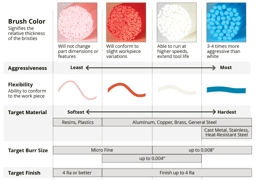
What Does Brush Color Mean?
Grinding power differs depending on brush color. All Xebec brushes are made from the same proprietary ceramic fibers manufactured into rods, or bristles, of different thicknesses. The greater the bristle thickness, the more aggressive the cutting action. Refer to the chart below and select brush color based on the workpiece material and burr root thickness.
How to Choose the Ideal Brush Size?
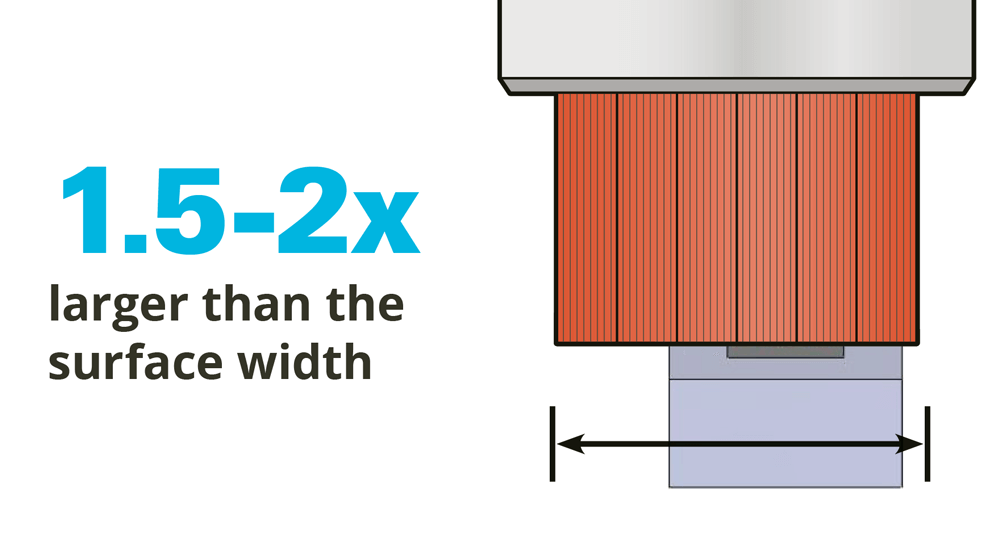
A smaller brush is the least expensive, but will require multiple passes. Use a larger brush to minimize cycle time. It is best to choose a brush size which is 1.5 to 2 times wider than the width of the surface of the workpiece. This allows the brush to engage the workpiece edge by 90° for optimal grinding power.
Brushes are available in multiple sizes and types ranging from 1 to 200mm in diameter.

How to Engage the Workpiece?
The brush cuts on the end, not the side. Cutting on the side of the brush will cause damage to the brush.
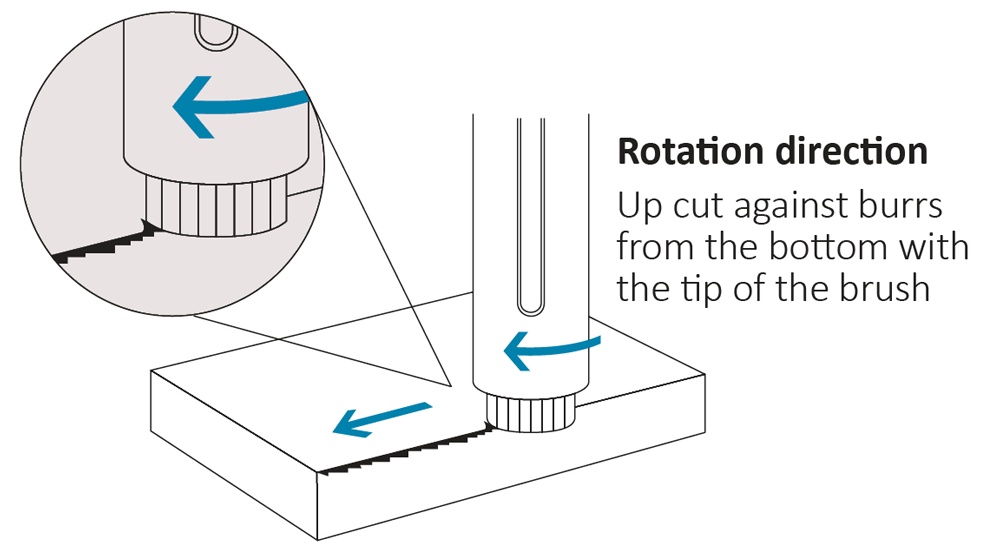
How to decide the direction of rotation?
Rotation direction should be up cutting. Grinding power is greater when the rotation direction of the front side of traveling is against the burr generation (climb milling).

What is Brush Projection?
When brush projection is shorter than 0.2 inches, the fibers are more rigid, which increases grinding power. When projection of the brush is greater than 0.2 inches, surface finish improves, which increases part contouring.
What Are the Key Operating Parameters for Cutting Fiber Brushes?
Brushes are used like other cutting tools. Always refer to the specific recommended starting operating parameters for the tool and material to determine starting speed, feed rate and depth of cut. After a successful test, performance may be improved by following the recommended adjustment increments.
RPM: Performs well between 60 – 80% of maximum RPM.
Depth of Cut: Usually set to between 0.020 – 0.060 inch D.O.C. depending on the burr direction.
Feed Rate: High feed rates can be achieved depending on the diameter of the brush and the material.
What is the Xebec Back Burr Cutter & Path?
Spherical deburring Cutter with a custom-made tool Path. For CNC deburring of entry and exit holes in a single pass.

Point Group Data
The point group data is provided by the set.

Deburring Amounts and Cumulative Error
Deburring amout is a width of an edge after deburring. 5 deburring amounts are provided for each Path data. Select a deburrig amount wchich fits into processsing accuracy of a hole diameter and position.

Make the cumulative errors of the positions between the main bore and cross hole, and the hole diameters as small as possible.
Product Code
Cutter Diameter (MM)
Deburring Amount (MM)
1
2
3
4
5
Allowable Cumulative Error (MM)
XC-08-A
0.8
0.02
0.04
0.06
0.8
0.1
0.03
XC-13-A
1.3
0.04
0.06
0.08
0.1
0.12
0.05
XC-18-A / B
1.8
0.07
0.09
0.11
0.13
0.15
0.08
XC-28-A / B
2.8
0.08
0.11
0.14
0.17
0.2
0.1
XC-38-A / B
3.8
0.09
0.13
0.17
0.21
0.25
0.12
XC-48-A / B
4.8
0.1
0.15
0.2
0.25
0.3
0.15
XC-58-A / B
5.8
0.1
0.15
0.2
0.25
0.3
0.18
Description of Xebec Path
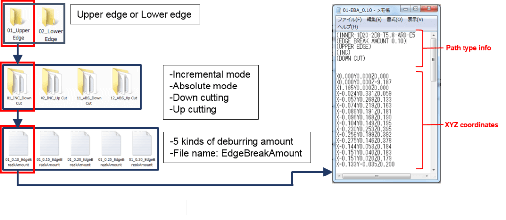
For machining center use, 1 Path data consists of 40 kinds of files.
- 2 edge type (upper and lower edge)
- 4 modes (incremental and absolute mode, down and up cutting)
- 5 deburring amounts
For combined lathe use, 1 Path data consists of 20 (XZY-axis) or 10 (XZC-axis) kinds of files.
Positioning of the Tool Length Offset
The point group data of the XEBEC Path is calculated based on the tip of the Cutter. Configure the tool length offset at the tip of the Cuttter. Otherwise, it may cause breakage of the Cutter or machinery.
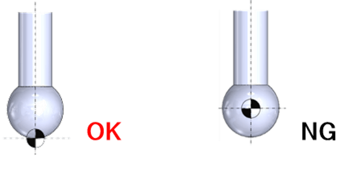
Start Point
Type B: Inner Diameter Upper & Lower Edges (Machining Center)
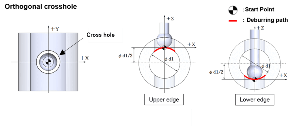
For the X and Y axes, set the start point to the center coordinate of the cross hole. For the Z axis, set the start point upward or down ward by the length of the radius of the main bore φ1 from the center coordinate. Prior to calling a XEBEC Back Burr Path program, make sure to position the Cutter to the start in all X,Y and Z axis. *For absolute mode paths, a start point is set as the origin of processing (X0, Y0, Z0)
Type BY: Inner diameter upper and lower edges (combined lathe XZY-axis)

If the diameter of the cross hole is equal to or greater than the diameter of the main bore. (For example, if the main bore is Φ10 mm and the cross hole is Φ10 mm or larger.)
Cross-Shaped Hole

If the diameter of the cross hole is more than 70% of the diameter of the main bore. (For example, if the main bore is Φ10 mm and the cross hole is Φ7 mm or larger.)
Always Use Xebec Products Safely
Cutting fiber brushes and stones are cutting tools and are often rotated at high speeds with a power tool or in a machine tool. They should never be operated at higher than the maximum speeds listed. When using these tools, safety glasses and gloves should be worn. Breathing the dust created by using these products for prolonged periods of time should be avoided. Please Note: Xebec Back Burr Cutter & Path is for CNC machines only. Never use it as a hand tool because the cutter may break and cause injury. Processing with a cutter of the wrong size may cause breakage of the product, tools or machinery. Make sure to verify the dimensions before use. Make sure that the run-out of the cutting edge is less than 0.01mm before beginning to process.

