Products
XEBEC Back Burr Cutter & Deburring Path™
XEBEC Back Burr Cutter - Neck Down Shank
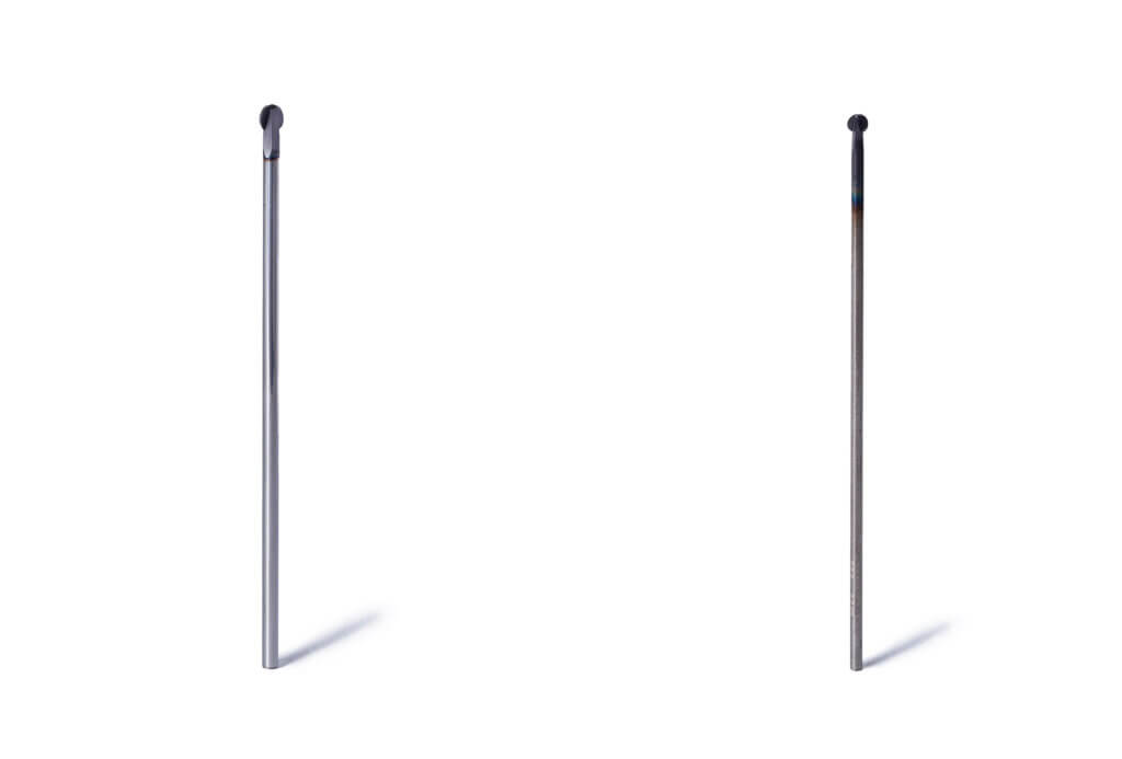
Spherical deburring Cutter with a custom-made tool Path. For CNC deburring of entry and exit holes in a single pass.

Show Tool Diameter and Length in: MM
in
EDP
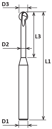
D3 Cutter Diameter (mm)
D1 Shank Diameter (mm)
D2 Neck Diameter (mm)
L1 Overall Length (mm)
L3 Neck Length (mm)
Blades
Product Number
Price
51000
0.8
3
0.48
60
4.2
2
XC-08-A
$191.68
51001
1.3
3
0.78
60
6.7
2
XC-13-A
$173.01
51002
1.8
3
1.1
60
8.2
2
XC-18-A
$153.67
51003
2.8
4
1.7
70
12.2
2
XC-28-A
$165.55
51004
3.8
4
2.4
70
16.2
2
XC-38-A
$171.31
51005
4.8
6
3
70
20.2
2
XC-48-A
$183.18
51006
5.8
6
3.5
70
24.2
2
XC-58-A
$193.03
51013
2.3
3
1.4
70
12.5
2
XC-23-A
$170.27
51014
3.3
4
2
70
17.5
2
XC-33-A
$174.15
51015
7.8
8
4.7
100
40
3
XC-78-A
$317.58
51016
9.8
10
5.9
120
50
3
XC-98-A
$450.76
EDP
D3 Cutter Diameter (in)
D1 Shank Diameter (in)
D2 Neck Diameter (in)
L1 Overall Length (in)
L3 Neck Length (in)
Blades
Product Number
Price
51000
0.031
0.118
0.019
2.362
0.165
2
XC-08-A
$191.68
51001
0.051
0.118
0.031
2.362
0.264
2
XC-13-A
$173.01
51002
0.071
0.118
0.043
2.362
0.323
2
XC-18-A
$153.67
51003
0.11
0.157
0.067
2.756
0.48
2
XC-28-A
$165.55
51004
0.15
0.157
0.094
2.756
0.638
2
XC-38-A
$171.31
51005
0.189
0.236
0.118
2.756
0.795
2
XC-48-A
$183.18
51006
0.228
0.236
0.138
2.756
0.953
2
XC-58-A
$193.03
51013
0.091
0.118
0.056
2.756
0.492
2
XC-23-A
$170.27
51014
0.13
0.157
0.079
2.756
0.689
2
XC-33-A
$174.15
51015
0.307
0.315
0.185
3.937
1.575
3
XC-78-A
$317.58
51016
0.385
0.394
0.232
4.724
1.969
3
XC-98-A
$450.76
All standard Cutters have a heat-resistant AITiCrN coating. But, each Neckdown style cutter is also available in an Uncoated version which provides a sharper cutting edge that is perfect for softer, stickier materials such as aluminum or plastic.
XEBEC Back Burr Cutter - Straight Shank
Show Tool Diameter and Length in: MM
in
EDP
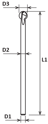
D3 Cutter Diameter (mm)
D1 Shank Diameter (mm)
L1 Overall Length (mm)
L2 Shank Length (mm)
Blades
Product Number
Price
51007
1.8
1.1
50
48.2
2
XC-18-B
$226.29
51008
2.8
1.7
70
67.2
2
XC-28-B
$236.12
51009
0.38
2.4
85
84.62
2
XC-38-B
$245.96
51010
4.8
3
105
100.2
2
XC-48-B
$265.63
51011
5.8
3.5
120
114.2
2
XC-58-B
$285.31
51017
2.3
1.4
60
57.7
2
XC-23-B
$245.87
51018
3.3
2
80
76.7
2
XC-33-B
$256.10
51019
7.8
4.7
150
142.2
3
XC-78-B
$491.74
51020
9.8
5.9
180
170.2
3
XC-98-B
$655.65
EDP
D3 Cutter Diameter (in)
D1 Shank Diameter (in)
L1 Overall Length (in)
L2 Shank Length (in)
Blades
Product Number
Price
51007
0.071
0.043
1.969
1.898
2
XC-18-B
$226.29
51008
0.11
0.067
2.756
2.646
2
XC-28-B
$236.12
51009
0.15
0.094
3.346
3.331
2
XC-38-B
$245.96
51010
0.189
0.118
4.134
3.945
2
XC-48-B
$265.63
51011
0.228
0.138
4.724
4.496
2
XC-58-B
$285.31
51017
0.091
0.056
2.362
2.272
2
XC-23-B
$245.87
51018
0.13
0.079
3.149
3.02
2
XC-33-B
$256.10
51019
0.307
0.185
5.906
5.599
3
XC-78-B
$491.74
51020
0.385
0.232
7.087
6.701
3
XC-98-B
$655.65
XEBEC Back Burr Cutter - Uncoated


Show Tool Diameter and Length in: MM
in
EDP
D3 Cutter Diameter (mm)
D1 Shank Diameter (mm)
D2 Neck Diameter (mm)
L1 Overall Length (mm)
L3 Neck Length (mm)
Blades
Product Number
Price
51032
0.8
3
0.48
60
4.2
2
XC-08-N
$201.13
51033
1.3
3
0.78
60
6.7
2
XC-13-N
$182.27
51034
1.8
3
1.1
60
8.2
2
XC-18-N
$161.33
51035
2.3
3
1.4
70
12.5
2
XC-23-N
$171.81
51036
2.8
4
1.7
70
12.2
2
XC-28-N
$173.90
51037
3.3
4
2
70
17.5
2
XC-33-N
$176.00
51038
3.8
4
2.4
70
16.2
2
XC-38-N
$180.18
51039
4.8
6
3
70
20.2
2
XC-48-N
$192.75
51040
5.8
6
3.5
70
24.2
2
XC-58-N
$203.23
51041
7.8
8
4.7
100
40
3
XC-78-N
$320.55
51042
9.8
10
5.9
120
50
3
XC-98-N
$456.73
EDP
D3 Cutter Diameter (in)
D1 Shank Diameter (in)
D2 Neck Diameter (in)
L1 Overall Length (in)
L3 Neck Length (in)
Blades
Product Number
Price
51032
0.031
0.118
0.019
2.362
0.165
2
XC-08-N
$201.13
51033
0.051
0.118
0.031
2.362
0.264
2
XC-13-N
$182.27
51034
0.071
0.118
0.043
2.362
0.323
2
XC-18-N
$161.33
51035
0.091
0.118
0.056
2.756
0.492
2
XC-23-N
$171.81
51036
0.11
0.157
0.067
2.756
0.48
2
XC-28-N
$173.90
51037
0.13
0.157
0.079
2.756
0.689
2
XC-33-N
$176.00
51038
0.15
0.157
0.094
2.756
0.638
2
XC-38-N
$180.18
51039
0.189
0.236
0.118
2.756
0.795
2
XC-48-N
$192.75
51040
0.228
0.236
0.138
2.756
0.953
2
XC-58-N
$203.23
51041
0.307
0.315
0.185
3.937
1.575
3
XC-78-N
$320.55
51042
0.385
0.394
0.232
4.724
1.969
3
XC-98-N
$456.73
XEBEC Back Burr Cutter - 3-Bladed Short

Show Tool Diameter and Length in: MM
in
EDP
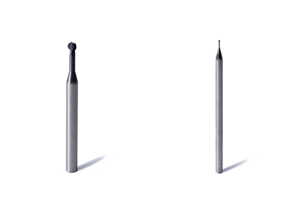
D3 Cutter Diameter (mm)
D1 Shank Diameter (mm)
D2 Neck Diameter (mm)
L1 Overall Length (mm)
L3 Neck Length (mm)
Blades
Product Number
Price
51021
0.8
3
0.48
60
3
3
XC-08-AS-3F
$245.13
51022
1.3
3
0.78
60
5
3
XC-13-AS-3F
$222.08
51023
1.8
3
1.1
60
6
3
XC-18-AS-3F
$196.94
51024
2.3
3
1.4
70
7.5
3
XC-23-AS-3F
$209.51
51025
2.8
4
1.7
70
9
3
XC-28-AS-3F
$211.61
51026
3.3
4
2
70
10.5
3
XC-33-AS-3F
$213.70
51027
3.8
4
2.4
70
12
3
XC-38-AS-3F
$219.99
51028
4.8
6
3
70
15
3
XC-48-AS-3F
$234.66
51029
5.8
6
3.5
70
18
3
XC-58-AS-3F
$247.23
51030
7.8
8
4.7
100
24
3
XC-78-AS-3F
$389.69
51031
9.8
10
5.9
120
30
3
XC-98-AS-3F
$553.10
EDP
D3 Cutter Diameter (in)
D1 Shank Diameter (in)
D2 Neck Diameter (in)
L1 Overall Length (in)
L3 Neck Length (in)
Blades
Product Number
Price
51021
0.031
0.118
0.019
2.362
0.118
3
XC-08-AS-3F
$245.13
51022
0.051
0.118
0.031
2.362
0.197
3
XC-13-AS-3F
$222.08
51023
0.071
0.118
0.043
2.362
0.236
3
XC-18-AS-3F
$196.94
51024
0.091
0.118
0.056
2.756
0.295
3
XC-23-AS-3F
$209.51
51025
0.11
0.157
0.067
2.756
0.354
3
XC-28-AS-3F
$211.61
51026
0.13
0.157
0.079
2.756
0.413
3
XC-33-AS-3F
$213.70
51027
0.15
0.157
0.094
2.756
0.472
3
XC-38-AS-3F
$219.99
51028
0.189
0.236
0.118
2.756
0.591
3
XC-48-AS-3F
$234.66
51029
0.228
0.236
0.138
2.756
0.709
3
XC-58-AS-3F
$247.23
51030
0.307
0.315
0.185
3.937
0.945
3
XC-78-AS-3F
$389.69
51031
0.385
0.394
0.232
4.724
1.181
3
XC-98-AS-3F
$553.10
Xebec Path

Let us create the path data for your Xebec® Back Burr Cutter application. Xebec® Path data is guaranteed for burr free performance and maximum tool life. Get started now by using our fast online assessment tool.
How to Order
To Get Started Complete the Free Online Assessment for Path
You can check whether XEBEC Back Burr Cutter and Path can be implemented on your workpiece and machining equipment. The result is immediately available.
The assessment will evaluate one program for each submission. Some applications may require multiple programs.
NOTE:
Select “Combined Lathe” if the machine uses the X-Axis to control diameter.
Select “Automatic Lathe” if the machine uses the Y-Axis to control diameter.
After completing the assessment, Xebec will determine if it is a successful application and recommend a cutter type based on the information provided. After placing an order through your distributor, the Path data file will be created and sent to the customer for review and approval. Xebec guarantees the path to perform without secondary burrs.
Custom Path
We can also create custom path data for the most complex edge profiles.
Send us an email today to get started on a non-standard path:
Features of Xebec Back Burr Cutter & Path™
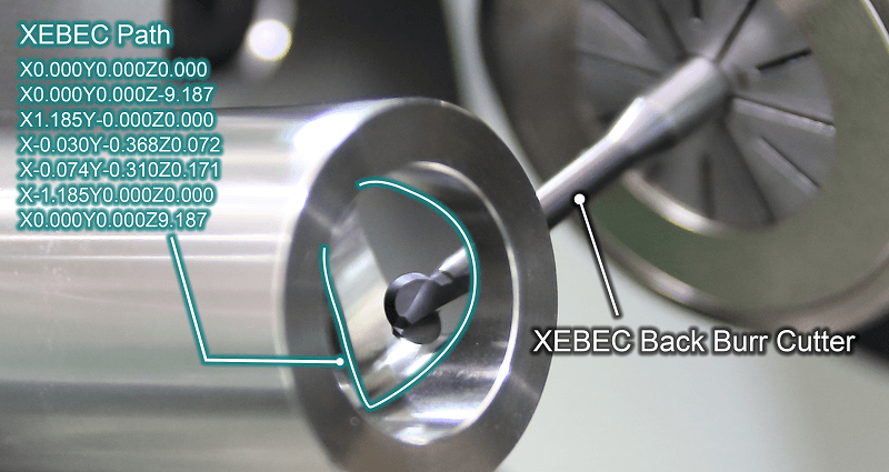
XEBEC’s innovative software enables back burring on a 3D curved surface in combination with the uniquely designed Cutter. The path data can be used as soon as being installed on a NC program, saving your time to make your own program.
Learn more about this unique solution in this article from our Learning Center Blog: The Xebec Back Burr Cutter & Path – A Consistent Path to Excellence
Uniform Edge Shape by Consistent Deburring Amount


Faster Operating Time Thanks to the Unique Cutter Design
Long Tool Life by Using the Entirety of the Cutting Blade
The contact points of the spherical cutting edge is continuously shifting. The red part shows the range of the blade use.
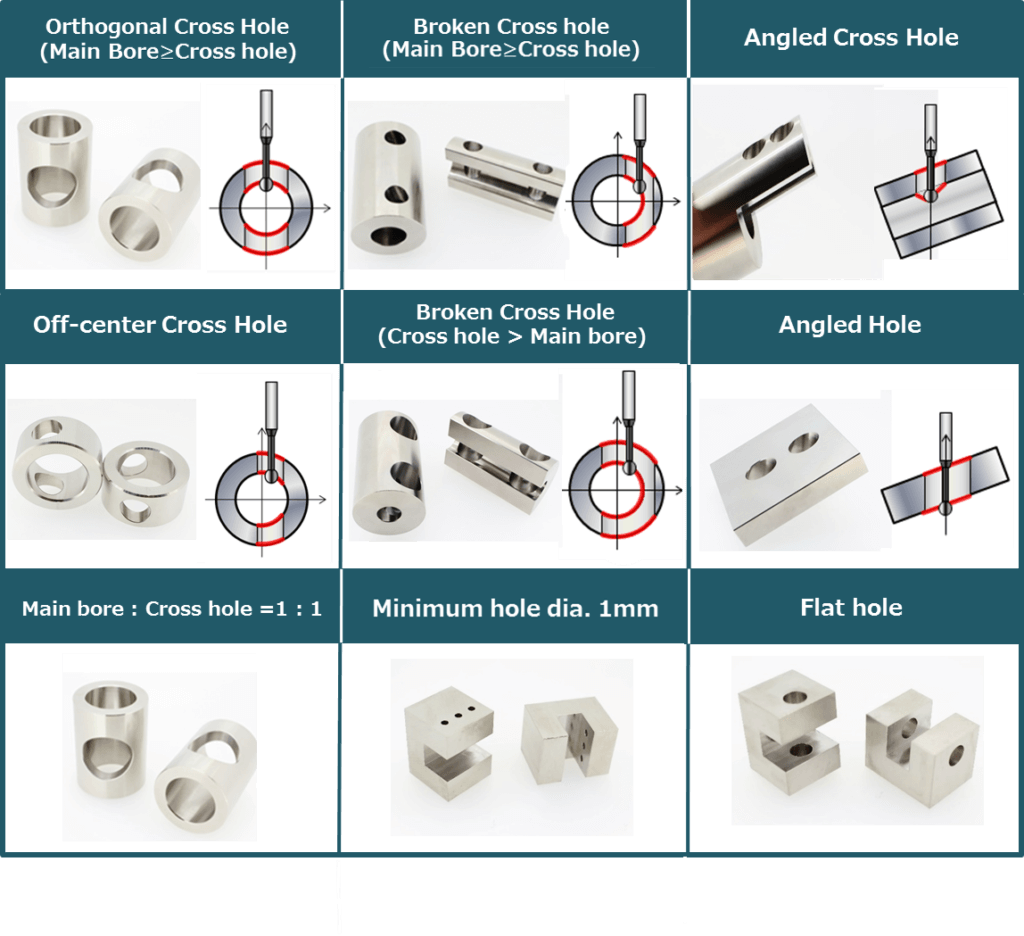
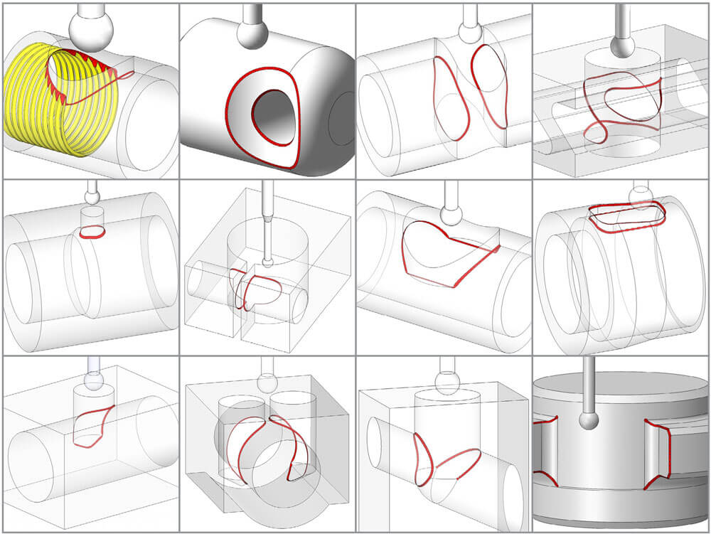
Applicable Areas

Features of Xebec Back Burr Cutte
- Micro-grain cemented carbide: Sharp and long lasting
- Highly heat-resistant AlTiCrN coating: Support materials from non-ferrous (e.g. aluminum) to difficult-to-cut materials (e.g. titanium and inconel)
- Helical Blade: Cleaner cutting edge and prevent secondary burrs
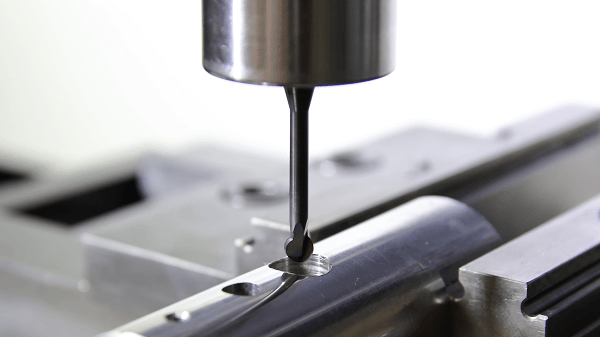
Applicable Equipment
The tool can be mounted on machining center (XYZ-axis) or combined lathe (XZY or XZC-axis). 3-axis simultaneous control is required. For combined lathe, polar coordinate interpolation is required. It cannot be used maually.
How to Use
Please refer to the instruction manual before use.
Path Setup
Please refer to the Xebec Back Burr Cutter & Path™ Setup Guide

Point Group Data
The point group data is provided by the set.

Deburring Amounts and Cumulative Error
Deburring amout is a width of an edge after deburring. 5 deburring amounts are provided for each Path data. Select a deburrig amount wchich fits into processsing accuracy of a hole diameter and position.

Make the cumulative errors of the positions between the main bore and cross hole, and the hole diameters as small as possible.
Product Code
Cutter Diameter (MM)
Deburring Amount (MM)
1
2
3
4
5
Allowable Cumulative Error (MM)
XC-08-A
0.8
0.02
0.04
0.06
0.8
0.1
0.03
XC-13-A
1.3
0.04
0.06
0.08
0.1
0.12
0.05
XC-18-A / B
1.8
0.07
0.09
0.11
0.13
0.15
0.08
XC-28-A / B
2.8
0.08
0.11
0.14
0.17
0.2
0.1
XC-38-A / B
3.8
0.09
0.13
0.17
0.21
0.25
0.12
XC-48-A / B
4.8
0.1
0.15
0.2
0.25
0.3
0.15
XC-58-A / B
5.8
0.1
0.15
0.2
0.25
0.3
0.18
Description of Xebec Path
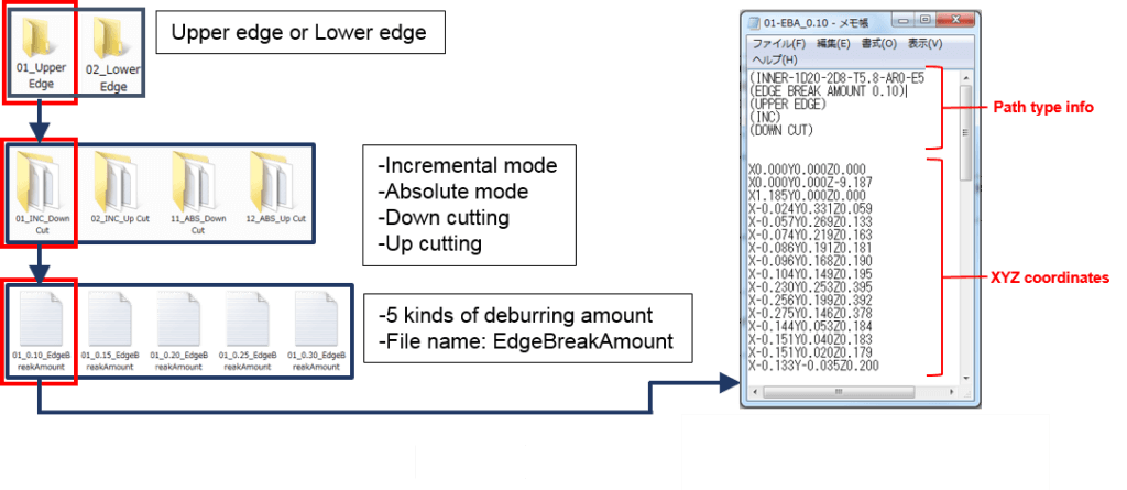
For machining center use, 1 Path data consists of 40 kinds of files.
- 2 edge type (upper and lower edge)
- 4 modes (incremental and absolute mode, down and up cutting)
- 5 deburring amounts
For combined lathe use, 1 Path data consists of 20 (XZY-axis) or 10 (XZC-axis) kinds of files.
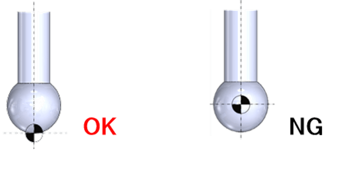
Positioning of the Tool Length Offset
The point group data of the XEBEC Path is calculated based on the tip of the Cutter. Configure the tool length offset at the tip of the Cuttter. Otherwise, it may cause breakage of the Cutter or machinery.
Start Point
Type B: Inner Diameter Upper & Lower Edges (Machining Center)
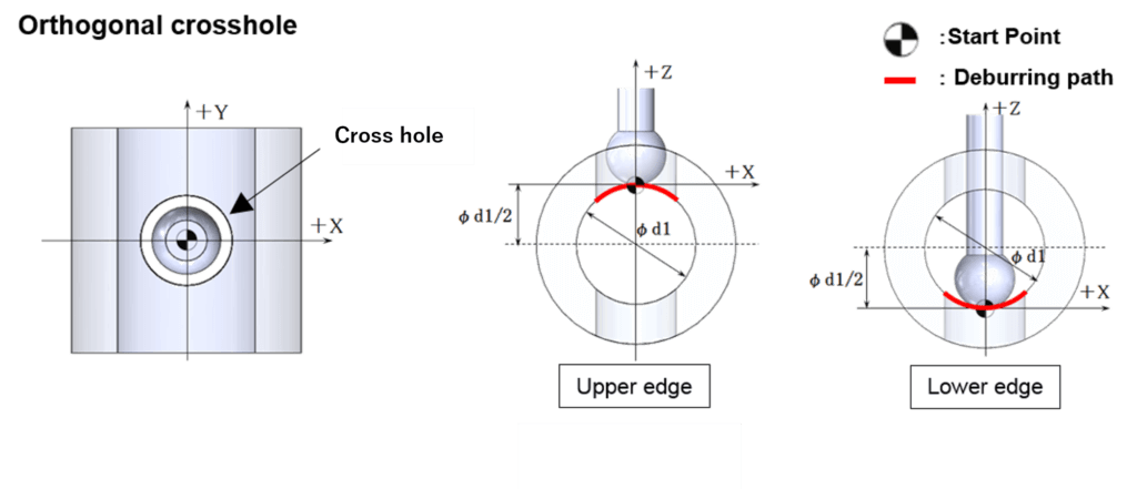
For the X and Y axes, set the start point to the center coordinate of the cross hole. For the Z axis, set the start point upward or down ward by the length of the radius of the main bore φ1 from the center coordinate. Prior to calling a XEBEC Back Burr Path program, make sure to position the Cutter to the start in all X,Y and Z axis. *For absolute mode paths, a start point is set as the origin of processing (X0, Y0, Z0)
Type BY: Inner diameter upper and lower edges (combined lathe XZY-axis)

If the diameter of the cross hole is equal to or greater than the diameter of the main bore. (For example, if the main bore is Φ10 mm and the cross hole is Φ10 mm or larger.)
Cross-Shaped Hole

If the diameter of the cross hole is more than 70% of the diameter of the main bore. (For example, if the main bore is Φ10 mm and the cross hole is Φ7 mm or larger.)
Process Conditions
The tool projection length is defined by cutter diameters (Dc). For example, for XC-18-B, 6Dc would be 10.8mm (6 x 1.8mm = 10.8).
Neck Down Shank Type
Product Code
Cutter Diameter (MM)
Projection Amount
Aluminum Alloy
Spindle Speed (Min-1)
Feed (mm/min)
Carbon Steel/Alloy Steel/Stainless Steel
Spindle Speed (Min-1)
Feed (mm/min)
XC-08-A
φ0.8
5Dc
20000
650
20000
600
XC-13-A
φ1.3
5Dc
20000
650
20000
600
XC-18-A
φ1.8
5Dc
20000
650
20000
600
XC-23-A
φ2.3
5Dc
18000
950
15000
750
XC-28-A
φ2.8
5Dc
15000
1400
12500
1000
XC-33-A
φ3.3
5Dc
12700
1250
10600
1050
XC-38-A
φ3.8
5Dc
11000
1600
9200
1200
XC-48-A
φ4.8
5Dc
8500
1100
7200
1100
XC-58-A
φ5.8
5Dc
7000
1600
4500
1350
XC-78-A
φ7.8
5Dc
5400
1350
4500
1350
XC-98-A
φ9.8
5Dc
4300
1300
3600
1150
Straight Shank Type
Product Code
Cutter Diameter (MM)
Projection Amount
Aluminum Alloy
Spindle Speed (Min-1)
Feed (mm/min)
Carbon Steel/Alloy Steel/Stainless Steel
Spindle Speed (Min-1)
Feed (mm/min)
XC-18-B
φ1.8
6Dc
9700
480
9700
480
XC-23-B
φ2.3
6Dc
7900
480
7900
480
XC-28-B
φ2.8
6Dc
6200
620
6200
620
XC-33-B
φ3.3
6Dc
5400
460
5400
460
XC-38-B
φ3.8
6Dc
4600
460
4600
460
XC-48-B
φ4.8
6Dc
3600
360
3600
360
XC-58-B
φ5.8
6Dc
3000
300
3000
300
XC-78-B
φ7.8
6Dc
1600
240
1600
240
XC-98-B
φ9.8
6Dc
1300
200
1300
200
1. When processing alumnium alloy, you can increase the spindle speed about twice the speed listed on the table above.
2. In order to improve processing result, change the spindle speed, table feed or deburring amount.
3. If the spindle speed and /or table feed fail to meet the standard conditions listed in the table, or an abnormal vibration or noise occurs, lower the spindle speed and table feed at an equel rate. Make sure to maintain the feed per rev (fn).
There are three reasons for long tool life of the Cutter; (1)it can maintain minimum cutting amount, (2)the contact point of the spherical cutting edge is continuously shifting, and (3)the Cutter is specially designed for deburring with high-quality material and coating.
The tool life depends on stiffness of workpiece or jig, machining accuracy, and burr size. According to the internal test, the Cutter lasts couple times longer than general carbide end mill.
No, we do not deal with cutting service.
No, it is not possible. If you re-grind the Cutter, the Cutter shape will be changed. Then the Cutter would not contact to the hole edge. We do not deal with re-grinding request.
Not only non-ferrous metal such as aluminum alloy, but also difficult-to-cut materials such as stainless steel or alloy steel can be processed.
According to our internal test, the Cutter could process aluminum alloy without creating build-up edge.
We haven’t performed any test with high hardness material.
Yes, but it depends on hardness of the burr.
If burr root thickness is smaller than the deburring amount, burrs can be removed by the Cutter. We prepare 5 kinds of deburring amount for each cutter diameter. Please refer to How to Use page for details.
We have no specified coolant. You can use coolant for other cutting tools (drilling, end mill etc.)
As same as other cutters, tool life will be extremely shortened for intermittent cutting.
Yes, you can purchase the Cutter from 1 unit.
The Cutter can be used with both flat surface holes and cross-holes, so you can combine each Path.
This is the cutting process, so that secondary burrs can occur in a precise way. However, the Cutter has excellent cutting ability, so that any secondary burrs will mostly not occur, unless the Cutter has been used heavily over time.
Deburring amount will vary and depends on the positioning gap of the workpiece, or runout of the Cutter. In theory, allowance of deburring amount is within 0.05mm.
Yes, you can buy only the Cutter. But we recommend you to use the Cutter and the Path together, because it will lead maximum effect for cutting quality and tool life.
If your machine doesn’t satisfy the recommended spindle speed, lower the spindle speed and table feed at an equal rate.
No. There is no expiration date.
No, it is prohibited to use any other kinds of tool besides the XEBEC Cutter, when using the XEBEC Path.
The deburring amount achieved with the Xebec Cutter and Path is one of a kind. But, in the case of a path by trigonometric function, the difference of deburring amount will be up to a few millimeters depending on combination of hole size. In the case of a path by CAD/CAM, it will take a long time to output path data.
No, you should not use the Cutter on a casting surface because of poor dimensional precision. It may leave burrs remaining or break the tool.
It depends on the level of dimensional precision, but it may leave burrs remaining or break the tool.
The path is typically delivered by CD. However, if you cannot use CD in relation with your drive, we will assist you to deliver by another digital method that fits your system.
Yes, it is possible to adjust coordinates. Make sure to use the incremental path and adjust the start point.
The Cutter and Path requires high-speed and high-accurate machining. It is recommended to use advanced preview control function.
Standard size is less than 5KB.
In case of cross hole with main bore dia.φ20mm and cross hole dia.Φ10mm, the number of program block will be approx. 80 lines, and program capacity is about 2KB. The number of program blocks can be twice that, depending on size combination between primary bore and cross-hole.
It is “.txt” format. You can edit the file by general document software on your PC.
The Path data contains coordinates data (e.g. X, Y, Z coordinates)only. Please add O number, G code, or M code by yourself. In addition, please note that feeding speed command (F code) is not included in our program.
No, it is not possible.

