Products
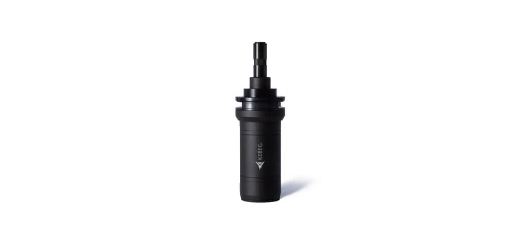
XEBEC Self-Adjusting Sleeve™
XEBEC Self-Adjusting Sleeve™
Completely automated, programmable brush length adjustment solution. Allows for unmanned operations and maintains optimal cutting efficiency with reduced downtime.
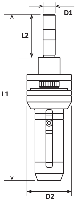

Tool Dimensions Shown: Metric
Inch
EDP
D1 Shank Diameter (mm)
D2 Neck Diameter (mm)
L1 Overall Length (mm)
L2 Shank Length (mm)
Weight (lbs)
Max RPM
Matching Sleeve (EDP)
Product Number
Price
50010
10
37
124.1
35
0.485 lbs
10,000
XP-AUT06M
50011
10
37
136.3
35
0.595 lbs
6,000
XP-AUT15M
50012
16
60
189
41.5
1.753 lbs
5,000
XP-AUT25M
50013
16
60
189
41.5
2.006 lbs
3,000
XP-AUT40M
EDP
D1 Shank Diameter (in)
D2 Neck Diameter (in)
L1 Overall Length (in)
L2 Shank Length (in)
Weight (lbs)
Max RPM
Matching Sleeve (EDP)
Product Number
Price
50010
0.394
1.457
4.886
1.378
0.485 lbs
10,000
XP-AUT06M
50011
0.394
1.457
5.366
1.378
0.595 lbs
6,000
XP-AUT15M
50012
0.630
2.362
7.441
1.634
1.753 lbs
5,000
XP-AUT25M
50013
0.630
2.362
7.441
1.634
2.006 lbs
3,000
XP-AUT40M
***This product has been discontinued***
*Each sleeve comes with the main body, brush mounting screws (M4 for XP-AUT25M & XP-AUT40M, 2pcs each), and a rack gear stand set
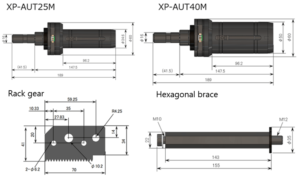
Tool Schematic
Applicable Equipment
XEBEC Self-Adjusting Sleeve™ must be mounted on an equipment which enables to stop and hold the sleeve at the fixed position.
XP-AUT06M & XP-AUT15M
The target hole diameter is between Φ3.5mm and Φ20mm. If you use the tool beyond the maximum rotation speed or outside the cylinder (outside the workpiece), it may result in brush breakage
Adjustment Amount
Predetermined length can be adjusted between 0.05mm to 1mm in 0.5mm increments in a single action.
How to Use
How to set XEBEC Self-Adjusting Sleeve™
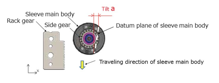
Example: If the sleeve main body travels in Y-direction of the rack gear
With the main spindle at its normal orientation angle, mount the sleeve on the main spindle so that the side gear of the sleeve is directed towards the rack gear. Then, check that the datum plane of the sleeve is parallel to the Y-axis. Ensure to adjust the “Tilt a” below 0.25mm.
How to Mount the Rack Gear
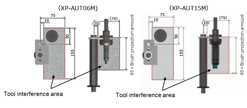
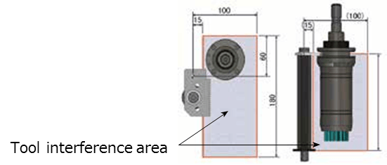
Mount the rack gear away from interferers (jigs, etc.) and in a position where an operating area (tool interfering area) can be ensured as shown in the figure below.
Securely fasten the hexagonal brace with the torque 40N/m on the slide table. Also, securely fasten the rack gear to the hexagonal brace with the torque 15N/m using a wrench. Otherwise, there is a risk of damaging the main body and/or the machine when the sleeve passes through the rack gear.
How to Decide Projection Adjustment Cycle
1. Figure out the amount of brush wear by process quantity or travel length
2. Set and execute the macro program so that the projection amount is adjusted at the predetermined interevals
Use Process Quantity; Cycle Time is More Important
Example:
Deburring an aluminum part
Travel length: 200mm per workpiece
Condition:
Brush wear: 2μm per workpiece
Brush wear: 0.2mm per 100 workpieces (Total ravel length 20,000mm)
Adjustment Cycle:
Set the cycle to every 100 workpiece (0.2mm brush wear)
Use Travel Length; Processing Quality is More Important
Example:
Finish processing of a cast-iron part’s edges
Travel length: 1500mm per workpiece
Condition:
Brush wear: 50μm (0.05mm) per workpiece
Adjustment Cycle:
Set the cycle to every 1500mm (50μm brush wear)

